⚙️ VexEngine - Custom Rendering Engine
February 13, 2026 (ongoing)
Links: Source Code · Rendered Images
VexEngine is a C++ graphics engine I built from scratch — featuring a progressive path tracer with CPU and GPU backends, Cook-Torrance GGX materials, BVH acceleration, denoising and a dockable editor UI. It supports both OpenGL and Vulkan through an abstracted rendering interface.
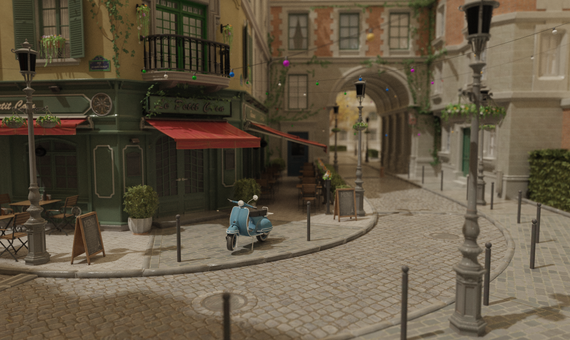
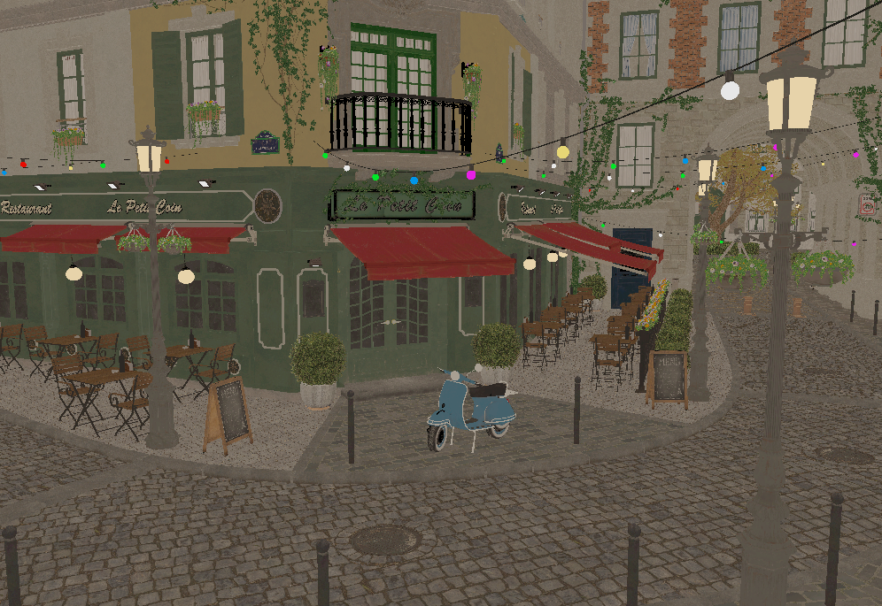
Scene: Nvidia Amazon Lumberyard Bistro (CC-BY 4.0)
After years of working within large frameworks like PBRT, where the overhead of navigating someone else's codebase often got in the way of actually experimenting, I wanted a clean, minimal engine that I fully understand and control. I have already worked with multiple rendering frameworks for teaching at KIT but VexEngine is built around my own experiments rather than a fixed curriculum.
Feature Checklist
Here is an overview of what is done and what I am planning to work on next:
Engine & UI
- Window creation with GLFW
- ImGui with docking for editor layout
- Scene hierarchy panel (n-level tree, drag-and-drop reparenting)
- Inspector panel
- Logging console
- Performance metrics (FPS, samples/sec for all path tracing modes)
- Object selection (hierarchy & viewport click)
- Outline rendering for selected objects
- Interactive camera (zoom, pan, orbit)
- Saving Framebuffer as image to disk
- Viewport gizmos (translate, rotate, scale in the viewport)
- Undo/redo system (command stack, Ctrl+Z/Y)
- Primitive objects (plane, cube, sphere, cylinder)
Scene & Assets
- OBJ mesh loading & deletion
- glTF loading (.gltf + .bin, full PBR/ARM texture support, node hierarchy)
- Runtime object transforms via inspector
- Environment map loading (HDR)
- FBX loading
- Scene serialization (save/load scenes to file)
Rendering and Global Illumination
- CMake compile flag to switch backends
- Live shader reload (F5 / button, OpenGL)
- Bounding Volume Hierarchy (BVH)
- Binned SAH Builder
- Ordered Traversal
- Fullscreen quad
- OpenGL
- Vulkan
- Shadow mapping (rasterizer, both backends)
- AABB-fitted orthographic frustum
- Receiver plane depth bias (RPDB)
- PCF 3×3 soft shadows
- Shadow map debug view in Sun inspector
- CPU Progressive Path Tracing
- GPU Progressive Path Tracing
- OpenGL (compute shader)
- Vulkan (compute shader, software BVH)
- Vulkan (VK_KHR_ray_tracing_pipeline, hardware RT cores)
- Path Tracing Features
- Next Event Estimation (NEE)
- Multiple Importance Sampling (MIS)
- Point light
- Directional (sun) light with soft shadows
- Emissive area lights
- Environment map lighting (importance-sampled)
- VNDF specular sampling (Heitz 2018)
- Russian Roulette path termination
- Firefly clamping
- Anti-aliasing (jittered sampling)
- Depth of field (thin-lens camera model)
- Debug visualization modes
- Denoising
- OIDN (Intel Open Image Denoise, CPU)
- Auxiliary buffer denoising (albedo + normal feature inputs)
- Deferred rendering
- Bidirectional Path Tracing (BDPT)
- Metropolis Light Transport (MLT)
- Photon Mapping
- Volumetric rendering (participating media)
- Spectral rendering
Materials
- Microfacet BSDF (GGX/Cook-Torrance) — handles both diffuse and specular lobes
- Mirror (perfect specular, delta BRDF)
- Dielectric (glass, Fresnel reflect/refract, delta BRDF)
- PBR parameter mapping from OBJ/MTL
- Textured materials
- Base Color / Albedo map
- Normal map
- Emissive map
- Roughness map (G channel of ARM, or separate greyscale)
- Metallic map (B channel of ARM, or separate greyscale)
- AO map (R channel of ARM, or separate greyscale)
- ARM-packed texture (single texture: R=AO, G=Roughness, B=Metallic)
- Alpha clip (cutout transparency from RGBA diffuse texture)
- Auto-smooth normals (angle-based)
Post-processing
- Exposure / gamma correction
- ACES tone mapping
- Bloom
- Chromatic Aberration
- Vignette
- Color Grading
Some of the features are further discussed below.
Editor
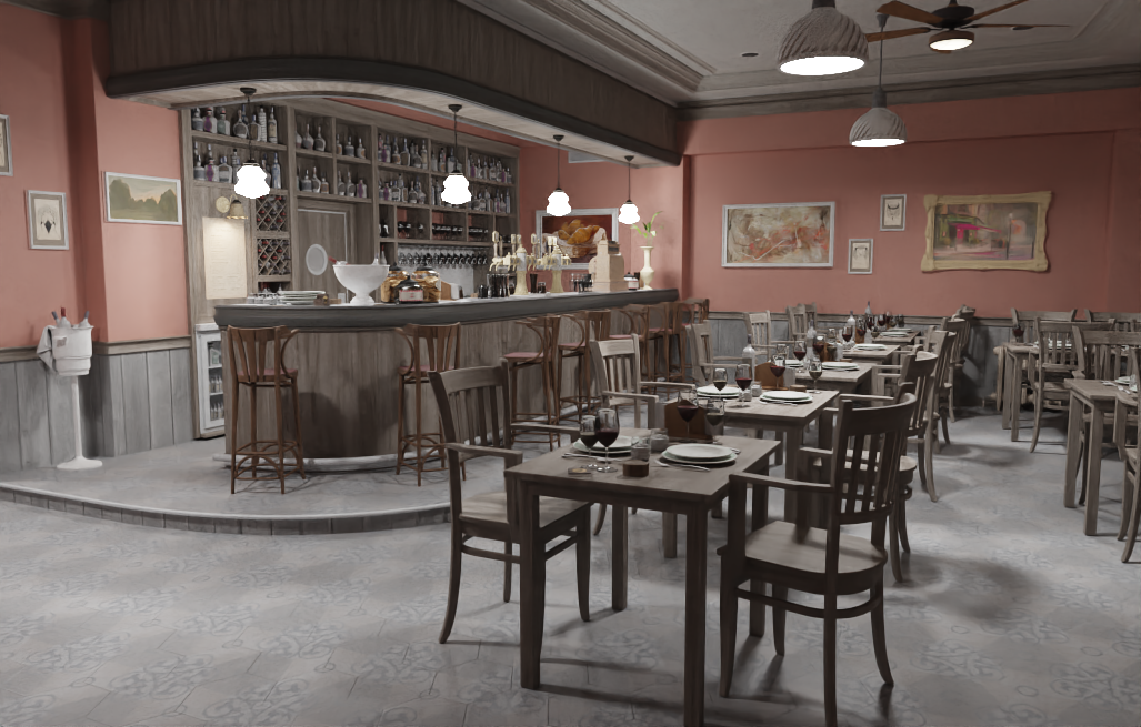
The foundation is GLFW for window creation and input handling, with Dear ImGui (docking branch) on top for the UI. Since ImGui is immediate-mode, the entire editor is just code — no widget trees, no event callbacks, just describe what you want each frame and move on. Every panel can be freely docked, undocked and resized.
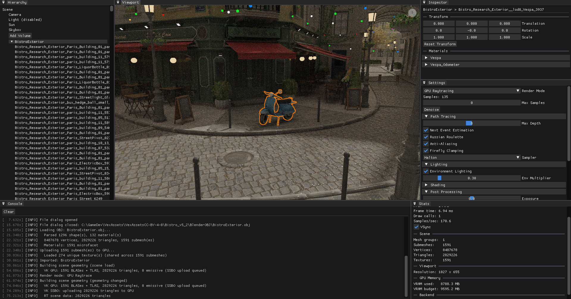
Scene: Nvidia Amazon Lumberyard Bistro (CC-BY 4.0)
The editor is built around five panels. The Scene Hierarchy is a free n-level tree: every node can be parented under any other by drag-and-drop, and the hierarchy updates immediately. OBJ files with multiple named objects are imported as a root node with one child per object name. Clicking a node selects it and syncs the viewport highlight. The Inspector exposes the selected node's local transform and material properties — base color tint, roughness, metallic, emissive strength, IOR — and lets you edit them live across all render backends. Each texture slot shows an inline thumbnail; hovering it pops up a larger preview so you can identify maps at a glance without leaving the inspector. The Console captures all engine output in real time, the Viewport is the main rendering view, and Stats shows a live dashboard: FPS, frame time, VSync toggle, current render mode, path tracer sample count and samples/sec, scene geometry counts (nodes, submeshes, triangles, vertices, textures, lights, emissive meshes, volumes), BVH node count and SAH cost, viewport resolution, and — on Vulkan — a per-category GPU memory breakdown (textures, geometry, framebuffers, ray tracing) against the driver's reported VRAM budget.
Navigating the scene feels like Blender: scroll to zoom, middle-mouse to pan, click-drag to orbit around a focus point. Meshes can be loaded at runtime via file dialog — OBJ via tinyobjloader, and glTF via tinygltf. glTF imports preserve the full node hierarchy from the file, creating one SceneNode per GLTF node under a named root. Materials are imported with full PBR data: ARM-packed metallicRoughnessTexture maps are automatically split across the AO (R), Roughness (G), and Metallic (B) slots with no redundant GPU copies.
OBJ Import Performance
Loading large scenes exposed three layered bottlenecks in the import pipeline, each fixed independently.
Double texture decode — Texture2D::createFromFile decoded each texture from disk for GPU upload, then rebuildRaytraceGeometry decoded the same files again from disk to build the CPU-side ray tracing data structures. For Bistro (274 unique textures) this meant 548 stbi_load calls. The fix: decode once with the rows unflipped, cache the raw pixels in a Scene::importedTexPixels map, flip the rows in-place for GPU upload, then let the ray tracing rebuild consume the cached pixels directly and clear the map when done.
Ray tracing SSBO size — All texture pixels are packed into a flat GPU buffer for the path tracer's texture array. At full resolution, Bistro's 274 textures produced a 3536 MB SSBO. Textures in the ray tracing SSBO are now capped at 1024 px per axis (nearest-neighbour downsample) before packing, reducing it to 884 MB with no visible quality difference at path-traced sample counts.
Sequential texture decode — After the above two fixes, the remaining bottleneck was the GPU upload phase: 274 textures decoded sequentially on the main thread before being uploaded. Since stbi_load is thread-safe for concurrent calls, all unique texture paths are now decoded in parallel across N worker threads (N = hardware concurrency) before the GPU upload begins. Each thread takes work from a shared atomic index, writes into a pre-allocated slot, and the main thread moves all results into importedTexPixels after joining — no locking required.
Measured on the Bistro exterior (1591 submeshes, 2.8M triangles, 274 textures) after each fix:
| State | GPU upload | Total import |
|---|---|---|
| After fixes 1 & 2 | 12 106 ms | 18.6 s |
| + parallel decode (28 threads) | 668 ms decode + 1 732 ms upload | 8.4 s |
The remaining ~5 s are tinyobjloader parsing (2.3 s) and SSBO/BVH packing (3.2 s), both sequential by nature.
Render-mode switch — Switching to a path tracing mode after loading triggers a geometry rebuild. The pixel cache is cleared after each rebuild to avoid holding ~3.5 GB of raw texture data permanently, so rebuilds previously re-read all 274 textures from disk (9.7 s). A prefetchTextures() call at the start of each rebuild re-fills the cache in parallel if empty, bringing the stall from 10.5 s to ~2.5–5 s depending on mode.
Double BVH build — The Compute and CPU path tracing modes built two identical BVHs: one inside CPURaytracer::setGeometry and a second m_rtBVH for triangle reordering in the GPU compute SSBO. Since both traverse scene.nodes in identical order, the resulting permutation is the same. getBVH() is now exposed on CPURaytracer, and m_rtBVH is assigned from it directly — saving ~2.2 s per Compute RT rebuild. CPU Raytrace and Compute Raytrace mode switches now take ~5 s; HW RT takes ~2.5 s.
Redundant RT→RT rebuilds — Every render-mode switch previously forced a full geometry rebuild, even when switching between two RT modes (e.g. CPU → Compute). The rebuild is only necessary when leaving rasterizer mode (gizmo edits are deferred there). RT→RT switches now skip the rebuild entirely; the existing m_cpuBVHDirty flag still triggers a rebuild when a mode needs the CPU BVH for the first time (e.g. HW RT → CPU RT). Switching between CPU RT and Compute RT is now instant.
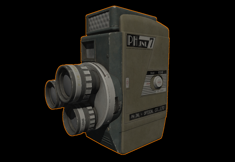
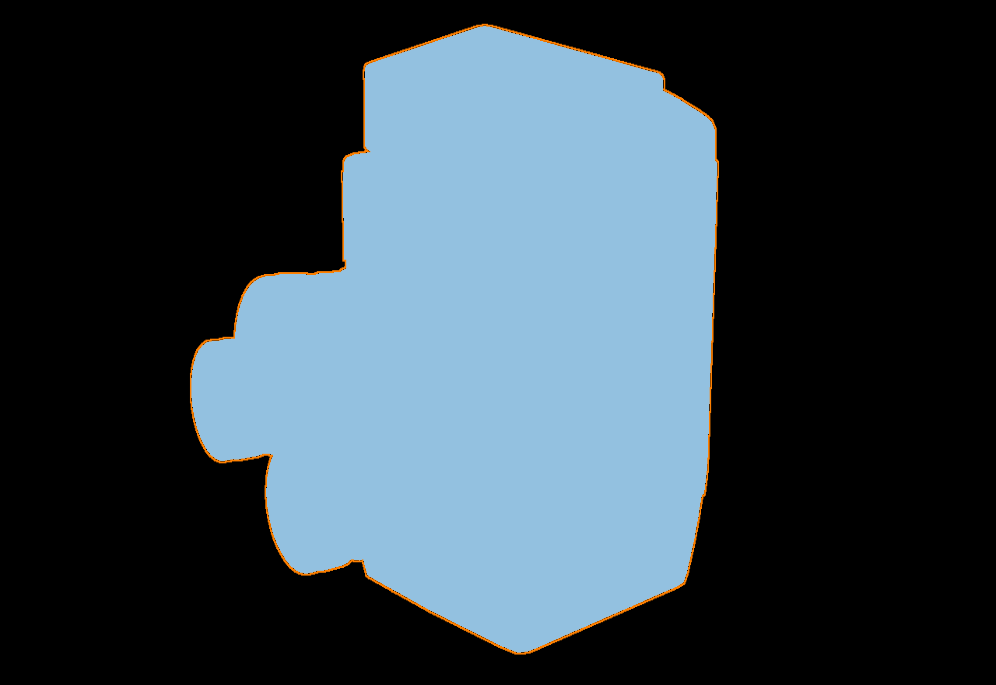
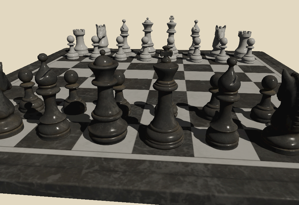
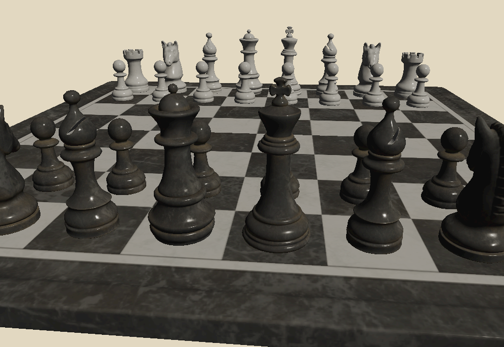
Clicking an object in the viewport highlights it with a screen-space outline: the selected geometry is rendered as a solid silhouette into an offscreen mask, which the tone-map pass then dilates with a 5×5 kernel and composites as an orange ring over the final image.
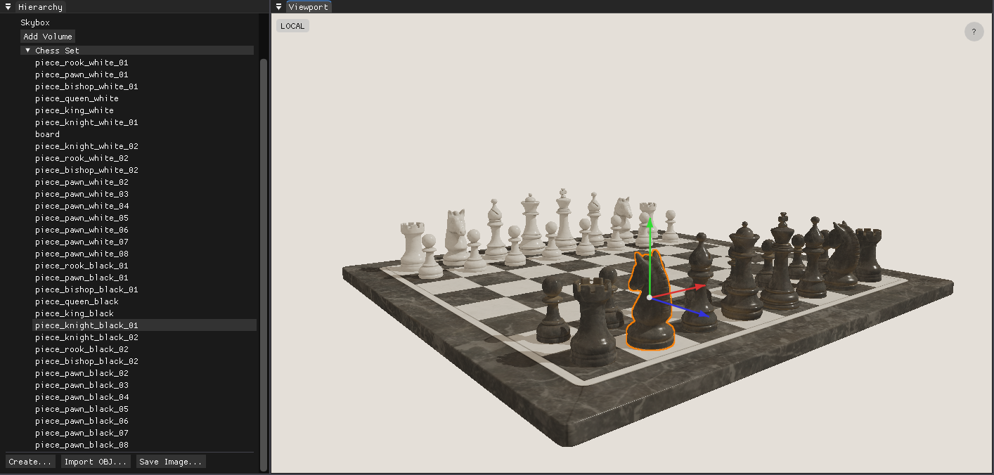
Scene: Chess Set (CC0)
Selected objects can also be transformed directly in the viewport: W for translate, E for rotate, R for scale, G to toggle local/global space. The gizmo is drawn using the ImGui draw list, so it requires no additional GPU passes. The pivot point is derived from the geometry's own AABB rather than the matrix origin, so scaling and rotating always feel anchored to the visual center of the object. All operations are recorded as undoable commands (Ctrl+Z / Ctrl+Y), and Ctrl+D duplicates the selected object. Primitive objects — plane, cube, UV sphere, and cylinder — can be created directly from the hierarchy panel.
Picking, Selection & Outline — Implementation Details
Shared infrastructure
- Left-click coordinates are captured from the ImGui viewport (top-left origin) and queued as a pick request.
pick()is called once per click and returns a{groupIdx, submeshIdx}pair that drives the selection state.- The selection feeds into a mask render pass every frame: selected geometry is drawn as solid white into a dedicated color-only framebuffer (
m_outlineMaskFB), even when nothing is selected (clear to black) so the image is always in a valid sampler state. - The outline composite runs inside the existing tone-map fullscreen pass. A 5×5 box dilation over the mask produces
ring = dilated × (1 − original), overlaid in orange on top of the tone-mapped image.
Picking
| OpenGL | Vulkan | |
|---|---|---|
| Method | GPU ID render + pixel readback | CPU Möller–Trumbore ray-triangle intersection |
| Resources | Dedicated m_pickShader, m_pickFB |
None — uses SceneMesh::meshData CPU vertices |
| Result | readPixel(x, y) − 1 → flat draw index → {group, submesh} |
Nearest-t triangle hit → {group, submesh} |
| GPU sync | glReadPixels stalls the pipeline |
Zero GPU involvement |
Outline mask rendering
| OpenGL | Vulkan | |
|---|---|---|
| Uniform order | bind() first, then setMat4() — glUniform* requires a bound program |
setMat4() first, then bind() — bind() flushes the UBO to the GPU |
| Depth test | Disabled explicitly (glDisable) and restored after |
Disabled via pipeline state at createPipeline(depthTest=false) |
| Image layout | Managed implicitly by the driver | Render pass transitions color attachment to SHADER_READ_ONLY_OPTIMAL at vkCmdEndRenderPass — no explicit barrier needed before sampling |
Outline composite
| OpenGL | Vulkan | |
|---|---|---|
| Mask binding | GL_TEXTURE1 + setInt("u_outlineMask", 1) |
setExternalTextureVK(slot=1) → descriptor set 2 (layout(set=2, binding=0)) |
| Enable flag | uniform bool u_enableOutline |
Push constant at byte offset 128 (layout(offset=128) uint enableOutline) |
| Flag dispatch | setBool → glUniform1i |
setBool → immediate vkCmdPushConstants |
Gizmo Implementation Details
All three modes operate in world space. The gizmo target is the selected scene node; the world matrix is resolved by walking the parent chain (getWorldMatrix = recursive parent × local). Write-back converts the new world matrix to local space via inverse(parentWorld) × newWorld.
Translate — A ray is cast from the camera through the cursor and projected onto the axis line. The offset accumulated is newWorld[3] += axis × worldDist, applied directly to the translation column. Using glm::translate instead would apply the offset in local space and produce wrong results when the object is rotated.
Rotate — A ray-plane intersection gives the cursor's hit point on the plane perpendicular to the rotation axis. An angle is read as atan2(cross · axis, dot) relative to a reference vector frozen at drag start, so the handle tracks the cursor continuously rather than snapping to an absolute angle.
Scale — Pivot preservation is handled analytically: after scaling the matrix, the translation column is corrected with newWorld[3] = pivot − newWorld × localCenter, where localCenter is the AABB center in local space frozen at drag start. This keeps the pivot stationary while the mesh grows. The center knob performs uniform scaling and is tested first in the hit list so it always takes priority over the axis handles.
Undo/redo — Every drag end emits a CmdSetTransform command pushed onto a 50-deep deque-based command stack. The command stores the before/after local matrices directly (no conversion needed at apply time). Hierarchy drag-and-drop emits a CmdReparent command that adjusts parentIndex, childIndices, and the local matrix to preserve world position. Ctrl+Z/Y walk the stack; Ctrl+D emits a CmdAddNode to duplicate the selected node as a sibling.
Dual Backend: OpenGL & Vulkan
One of the more unusual design decisions is supporting two graphics APIs, selected at compile time via a CMake flag. All GPU concepts — shaders, framebuffers, meshes, textures — sit behind a common interface; the application layer never calls any GL or VK functions directly. This forced me to think carefully about where abstraction boundaries belong, and made every feature run twice — a surprisingly effective way to catch design mistakes early.
OpenGL is the simpler backend and makes iteration fast: shader hot-reload works at the press of F5, and the driver handles a lot of state implicitly. Vulkan is far more explicit — render passes, descriptor sets, pipeline layouts, synchronization barriers — everything has to be declared. That verbosity is the price of admission for hardware ray tracing via VK_KHR_ray_tracing_pipeline, which wouldn't have been possible on the OpenGL side. vk-bootstrap handles instance and device setup, and VMA manages GPU memory allocation — both reduce boilerplate without hiding anything important.
 Rasterizer (OpenGL)
Path Tracer (Vulkan)
Rasterizer (OpenGL)
Path Tracer (Vulkan)
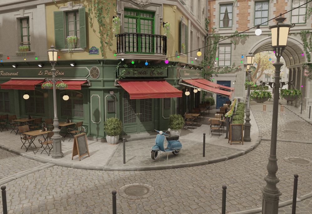
Scene: Nvidia Amazon Lumberyard Bistro (CC-BY 4.0)
Rasterization & Debug Views
Both backends support standard rasterization for fast interactive preview — the default mode for navigating the scene and placing objects before running a more expensive path trace. The rasterized image is rendered into an HDR intermediate framebuffer and then passed through a fullscreen tone-map pass that applies ACES tone mapping and exposure / gamma correction before display.
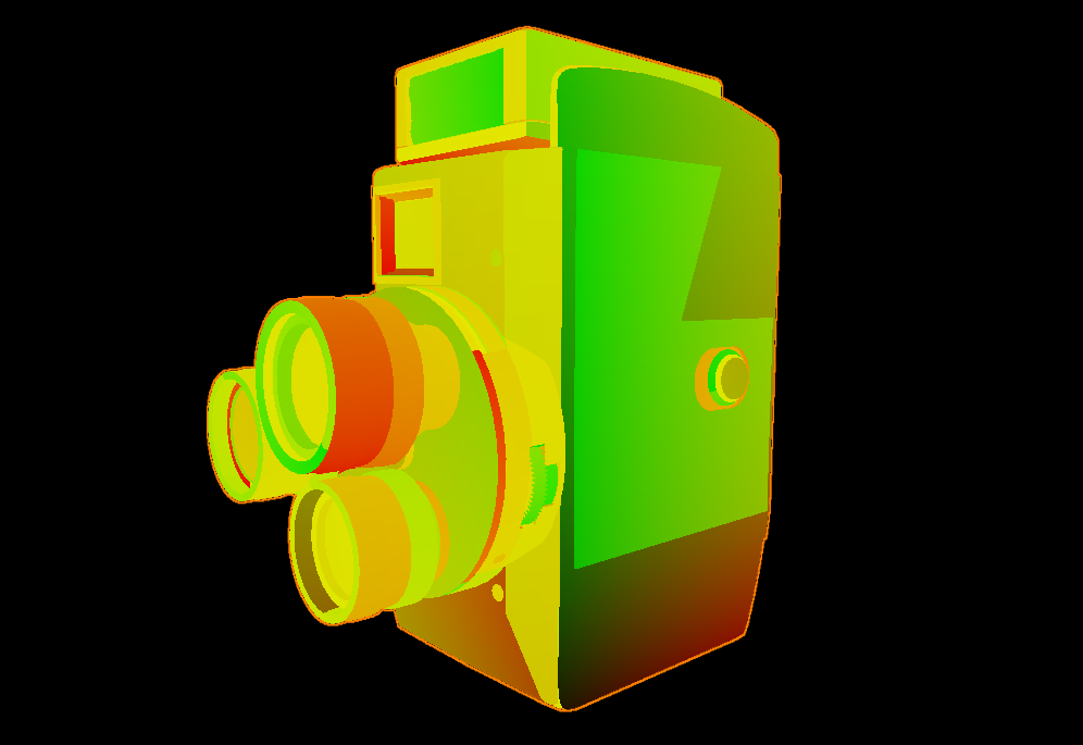
On top of the standard shaded view, several debug visualization modes can be toggled at any time from the viewport:
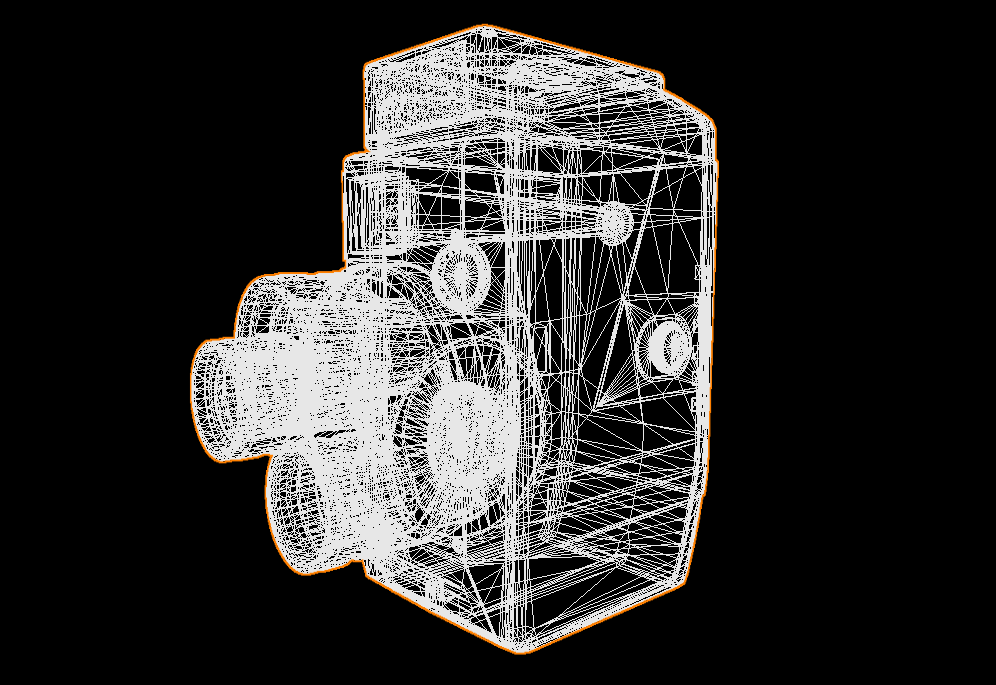
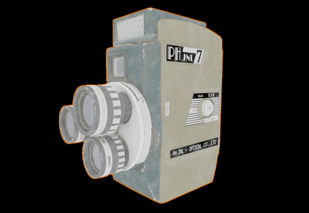
- Wireframe — Triangle mesh overlay for inspecting topology and geometry density.
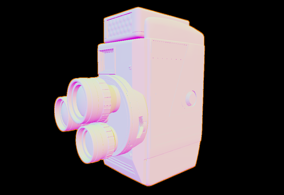
- Normals — Surface normals as RGB, useful for checking mesh quality and normal map correctness.
- Albedo / Emission / Material ID — Passes that isolate specific shading components for quick inspection.
- UVs — Texture coordinates as colors, good for spotting seams and mapping problems.
- Depth — Grayscale depth buffer, helpful for verifying near/far plane settings.
- Roughness / Metallic / AO — PBR channel isolation; reads the correct channel from ARM-packed textures (G/B/R respectively) or the scalar fallback.
Shadow Mapping
The rasterizer supports directional (sun) shadow mapping on both backends. A depth-only pass renders the scene from the sun's point of view into a 4096×4096 shadow map, which the main shading pass samples to determine whether each surface point is lit or in shadow. Soft shadows are produced by a PCF 3×3 kernel, and the shadow frustum is fitted tightly to the scene geometry so no texel resolution is wasted. Getting the bias right is the main challenge — the engine uses a combination of three complementary techniques that together eliminate both acne and peter-panning across a wide range of sun angles. A Normal Bias slider and an inline shadow map debug view are exposed directly in the Sun inspector.
 Shadows off
PCF shadow mapping
Shadows off
PCF shadow mapping
Scene: Chess Set (CC0)
Frustum Fitting & Bias
Frustum fitting — The orthographic frustum is fitted to the world-space AABB of all scene geometry. All eight AABB corners are projected into light view space and the exact min/max extents are read off directly — no wasted texels regardless of scene size or sun angle. The AABB is computed once at scene load and cached. A 2% scale from the AABB center adds a small margin to prevent PCF samples near the frustum edge from clamping to the border color.
Getting the bias right requires balancing two artifacts: too little causes self-shadowing acne, too much causes peter-panning (the shadow detaches from its caster). The engine uses three complementary techniques, matching the approach used by Unity and Godot:
- Normal offset bias — Instead of biasing the depth value, the shadow lookup point is shifted along the surface normal by
sin(θ) × normalBiasbefore projection.sin(θ) = sqrt(1 − NdotL²)is zero when the surface directly faces the light and maximum at grazing angles. The offset is expressed in shadow-map texel units and pre-multiplied by the world-space texel size on the CPU, so it scales automatically with frustum and scene size. - Receiver plane depth bias (RPDB) — The PCF 3×3 kernel samples at ±1 texel offsets. On a sloped receiver surface the correct reference depth differs at each tap. Using the same center depth for all nine samples causes acne on moderately-lit faces. RPDB computes
dZ/dUanddZ/dVvia screen-space derivatives (dFdx/dFdy) and adjusts each tap's reference depth to match the receiver slope analytically. - Hardware constant depth bias — A small constant bias (
glPolygonOffset/vkCmdSetDepthBias) applied during shadow map rendering handles the residual case whereNdotL ≈ 1and the normal offset is near zero. The slope-scale component is intentionally zero — at grazing angles it diverges and recreates the peter-panning that normal offset is designed to avoid.
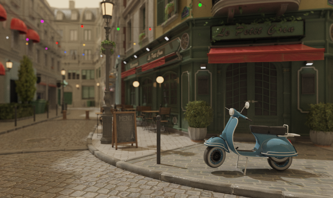
Path Tracing
The engine's main rendering mode is a progressive path tracer displayed in the viewport via a fullscreen quad. It accumulates samples silently in the background — the longer the scene sits still, the cleaner the image gets. Any change to the camera, geometry, or settings immediately resets the accumulation and starts fresh.

Ray-scene intersection is accelerated by a BVH built with binned SAH. The path tracer supports four light types — emissive geometry, emissive textures, point/directional lights, and an environment map — all sampled with Next Event Estimation (NEE) and Multiple Importance Sampling (MIS) to keep variance low. Path depth is managed by Russian Roulette, the specular lobe uses VNDF sampling (Heitz 2018), and depth of field is modelled with a thin-lens camera. Anti-aliasing comes for free via jittered primary rays, and firefly clamping suppresses extreme outliers during early convergence.
BVH Acceleration
The BVH is built with binned Surface Area Heuristic (SAH). The builder evaluates split candidates across binned intervals to produce a tree that minimises expected traversal cost. At query time, traversal is ordered — the closer child is visited first, improving early termination and reducing the number of intersection tests significantly.
Ray-Triangle Intersection Precision
The three software path tracers use Möller-Trumbore (MT) for ray-triangle intersection. MT computes the determinant a = dot(edge1, cross(dir, edge2)), which equals −dot(dir, geoNormal) × 2 × area. Two choices in the formulation directly affect numerical robustness at grazing angles.
Near-parallel epsilon — a approaching zero means the ray is nearly coplanar with the triangle. A naive absolute threshold rejects valid near-grazing intersections on small triangles because |a| = sin(θ) × 2 × area, so the effective minimum angle scales inversely with triangle size. The engine uses 1e-9, well below the range where floating-point division becomes unstable but permissive enough for genuinely shallow hits. The t-threshold (self-intersection guard) is kept separate at 1e-7 since it operates in world-space distance rather than determinant scale.
Barycentric bounds tolerance — Once a passes the epsilon check, f = 1/a can still be large at shallow angles, amplifying rounding error in the subsequent dot products for u and v. A ray landing exactly on a triangle edge can compute slightly outside [0, 1]. Rather than a strict simplex test, the engine allows 1e-5 of outward slack on all three edges. This is not clamped before use: the interpolated attributes (normals, UVs, tangents) are computed with the raw coordinates, since a 1e-5 extrapolation past an edge is imperceptible and adjacent triangles share the same vertex data at their boundary anyway.
Limitations — Both tolerances are absolute rather than relative to triangle size. On large triangles the 1e-9 epsilon still rejects extreme grazing angles; on very small triangles the 1e-5 UV slack is a proportionally larger fraction of the triangle and could admit a hit in a gap at a non-manifold edge or T-junction.
Light Sources & Sampling
- Emissive geometry — Triangles with a solid emissive color (
Ke) are treated as area lights. They are collected into a CDF weighted by surface area, allowing NEE to directly sample points on their surface each bounce. When a path ray hits one of these emitters it terminates — the surface is a pure light source. MIS balances NEE and BSDF sampling to reduce variance. - Emissive textures — Materials with
map_Keare handled differently. Because emission varies per-texel they are excluded from the light CDF and cannot be NEE-sampled. They contribute only when a ray happens to hit them, and unlike solid emitters they continue scattering via their base material — they are glowing surfaces, not light sources. - Point and directional lights — Sampled by dedicated NEE paths. Point lights use inverse-square falloff. The directional (sun) light has a configurable angular radius — shadow rays are jittered within a cone to produce soft shadows.
- Environment lighting — An HDR environment map provides image-based lighting. A 2D CDF (conditional + marginal) is precomputed so NEE preferentially samples bright sky regions. MIS balances environment and BSDF sampling.
All four NEE strategies fire independently each bounce. The emissive material contribution can be toggled off to isolate explicit light sources.
Russian Roulette Path Termination
After the first two bounces, each subsequent bounce computes a survival probability equal to the luminance of the current path throughput, capped at 0.95. The path terminates with probability 1 − p; if it survives, the throughput is divided by p to keep the estimator unbiased. Paths through dark surfaces lose energy quickly and self-terminate early; bright paths continue. Raising the maximum depth has little practical cost — most paths terminate long before the cap.
VNDF Specular Sampling
The specular lobe uses VNDF sampling (Heitz 2018) instead of plain NDF sampling. NDF sampling draws half-vectors without regard to the view direction, frequently producing reflected directions below the surface at grazing angles — wasting the sample and losing energy. VNDF restricts half-vectors to those visible from the current view direction, eliminating most invalid samples.
Depth of Field
Depth of field uses a thin-lens camera model. Instead of firing all rays from a single point (pinhole), each primary ray originates from a random position on a disk of configurable radius (the aperture), aimed at a focal plane at a configurable distance. Objects at the focal plane are perfectly sharp; objects nearer or farther accumulate a circle of confusion that grows with distance. Concentric disk mapping keeps the sample distribution uniform across the lens. Setting aperture to zero falls back to exact pinhole behaviour with no overhead. Both CPU and GPU path tracers share the same model.
The algorithm is the same across all four backends — the difference is where it runs:
- CPU — The original implementation, running on the host. Slow, but every ray can be stepped through in a debugger, which was invaluable when building out the lighting and sampling logic.
- GPU (OpenGL compute) — The same algorithm ported to a GLSL compute shader. Runs massively parallel with a significant speedup, and supports live shader reload (F5) for fast iteration.
- GPU (Vulkan compute) — Algorithmically identical to the OpenGL compute path, ported to Vulkan. Uses a CPU-built BVH uploaded as an SSBO and a single
pathtracer.compcompute shader dispatched in 8×8 workgroups. Works on any Vulkan device regardless of hardware RT support. - GPU (Vulkan HW RT) — Uses hardware ray tracing (
VK_KHR_ray_tracing_pipeline) with dedicated RT cores for BVH traversal and ray-triangle intersection. The algorithm spans five shader stages (rgen, rmiss, shadow rmiss, rchit, rahit) with an iterative loop in the ray generation shader to stay within a recursion depth of one.
Scene: Nvidia Amazon Lumberyard Bistro (CC-BY 4.0)
Volumetric Participating Media
The path tracer supports physically-based participating media — fog, haze, light shafts, and colored smoke — as first-class scene objects. Volumes are axis-aligned bounding boxes placed anywhere in the scene, or set to infinite mode for global atmospheric effects. Each volume has three parameters: density (σt, the extinction coefficient), scatter color (per-channel scattering albedo, so volumes can be tinted), and anisotropy (the Henyey-Greenstein g parameter, controlling whether light scatters forward, backward, or isotropically).
The implementation is fully analytical — no additional geometry, BVH nodes, or TLAS instances. Every path tracing bounce intersects each volume against the ray using a slab test. If the ray enters a volume, a free-flight distance is drawn by exponential importance sampling. If that distance falls before the surface hit, a scatter event occurs: the throughput is weighted by the scattering albedo, a new direction is drawn from the Henyey-Greenstein distribution, and NEE fires toward all active lights using the phase function as the directional weight. If no scatter occurs within the slab, Beer-Lambert transmittance attenuates the throughput by exp(−σt × path length) before the ray continues to the surface.
Anisotropy (g) shapes the scattering lobe: g = 0 gives isotropic fog, g → +1 concentrates scattering forward and produces glowing halos around lights visible through haze, and g < 0 scatters back toward the source.
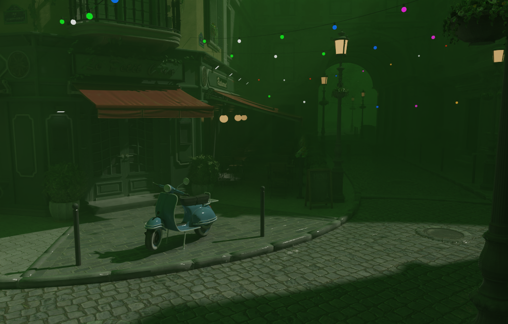
Scene: Nvidia Amazon Lumberyard Bistro (CC-BY 4.0)
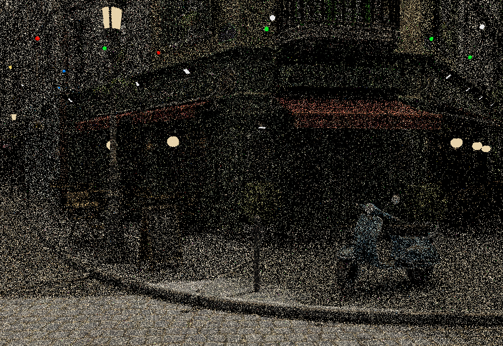
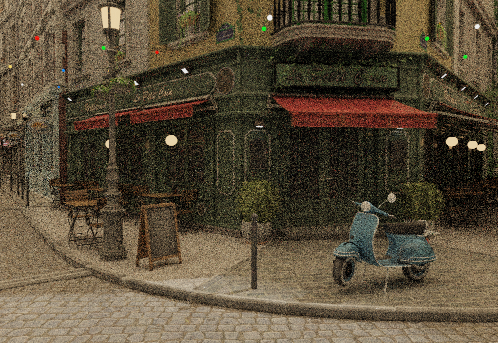
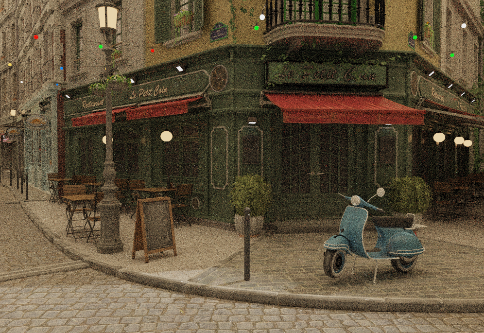
Denoising
Even a well-optimised path tracer needs many samples before the image looks clean — at 1 SPP the noise is severe, and reaching a perceptually converged result can take hundreds of passes. Rather than waiting, the engine integrates Intel Open Image Denoise (OIDN) as a one-click post-process that runs on the CPU and produces a clean result in a fraction of a second.
The integration works entirely on the CPU side and is backend-agnostic. A "Denoise" button appears in the Settings panel whenever samples have been accumulated; pressing it reads back the current accumulation buffer as linear HDR float RGB — before any tone mapping — feeds it into OIDN's RT filter, then applies the same exposure, ACES tone mapping and gamma correction as the live display. The result replaces the viewport image and accumulation is frozen. Moving the camera or changing any scene parameter immediately clears the denoised result and restarts accumulation from zero.
For both Vulkan GPU path tracers (HW RT and compute) the readback copies the RGBA32F accumulation image from device memory to a CPU-side staging buffer via an immediate-submit command, divides out the per-pixel sample counter stored in the alpha channel, and passes the resulting linear HDR data directly to OIDN. For the CPU path tracer the accumulation buffer is already on the host, so no copy is needed.
A second Denoise+ mode feeds OIDN two additional feature buffers — first-hit albedo and first-hit world-space normal — alongside the noisy colour input. OIDN's RT filter uses these to separate lighting noise from surface texture and to respect geometric edges, dramatically improving denoising quality at very low sample counts where colour-only denoising struggles. Each backend captures the data at the primary ray hit: the GPU path tracers write it to dedicated rgba32f storage images at depth 0 in the shader; the CPU path tracer stores it in per-pixel auxiliary buffers filled on the first bounce. Both buffers are constant across samples (first-hit data is deterministic), so writing every frame incurs no overhead. The comparison below was captured at 1 SPP — a single sample per pixel.
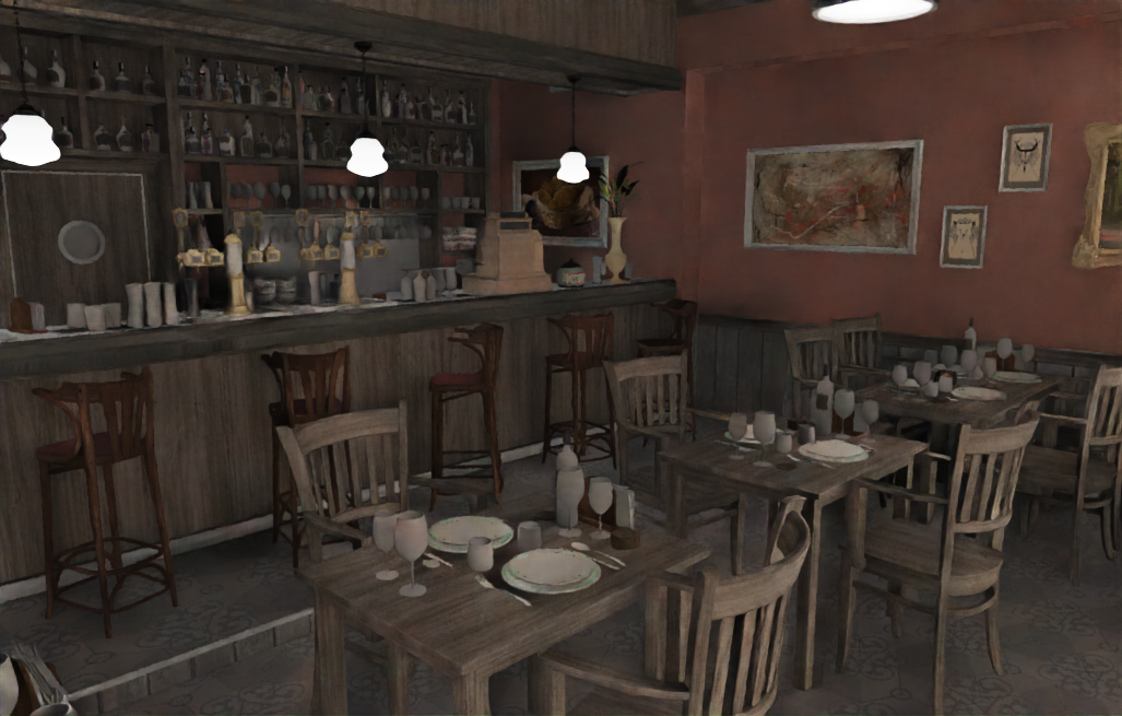
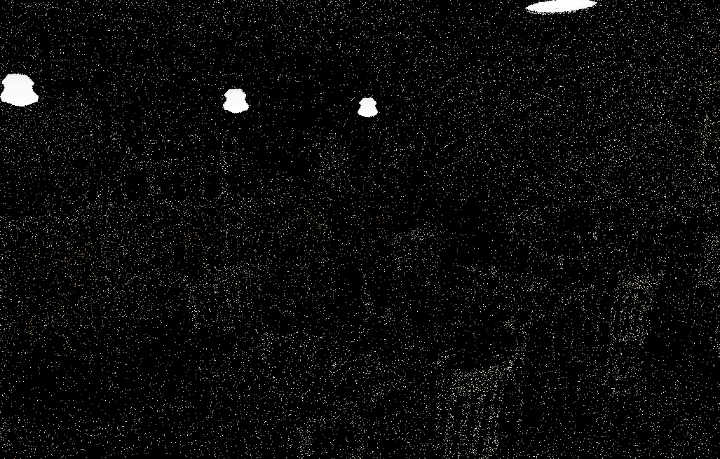 1 SPP (raw)
Denoise+ (albedo + normal)
1 SPP (raw)
Denoise+ (albedo + normal)
Scene: Nvidia Amazon Lumberyard Bistro (CC-BY 4.0)
Post-Processing
The post-processing stack sits between the HDR render and the final display output. Every render path — rasterizer and path tracer, OpenGL and Vulkan — shares the same pipeline: bloom composited in linear HDR space, then ACES tone mapping and exposure / gamma correction in a single fullscreen pass.
Bloom runs as a three-stage pipeline on a half-resolution offscreen framebuffer:
-
Threshold — A fragment shader reads the HDR source, converts each pixel to luminance, and applies a soft ramp: pixels below the threshold contribute nothing, pixels above it contribute proportionally to how far they exceed it. Only bright surfaces — emissive materials, specular highlights, direct light hits — pass through.
-
Separable Gaussian blur — A pair of ping-pong framebuffers alternate horizontal and vertical 9-tap Gaussian passes (σ ≈ 1.5). Running the blur multiple times spreads the glow further without a wider kernel.
-
Composite — The blurred bloom map is additively mixed onto the HDR image at a configurable intensity, before tone mapping is applied. Compositing in HDR space means the glow from an overexposed surface stays bright through the tone mapper rather than getting clipped to a flat white halo.
One complication arises with the GPU path tracers: the accumulation buffer stores a running sum across N samples, not a normalised average. The threshold shader divides by the sample count before extracting bright pixels — without this, the bloom contribution would grow linearly with N and blow the image out to white after enough samples.
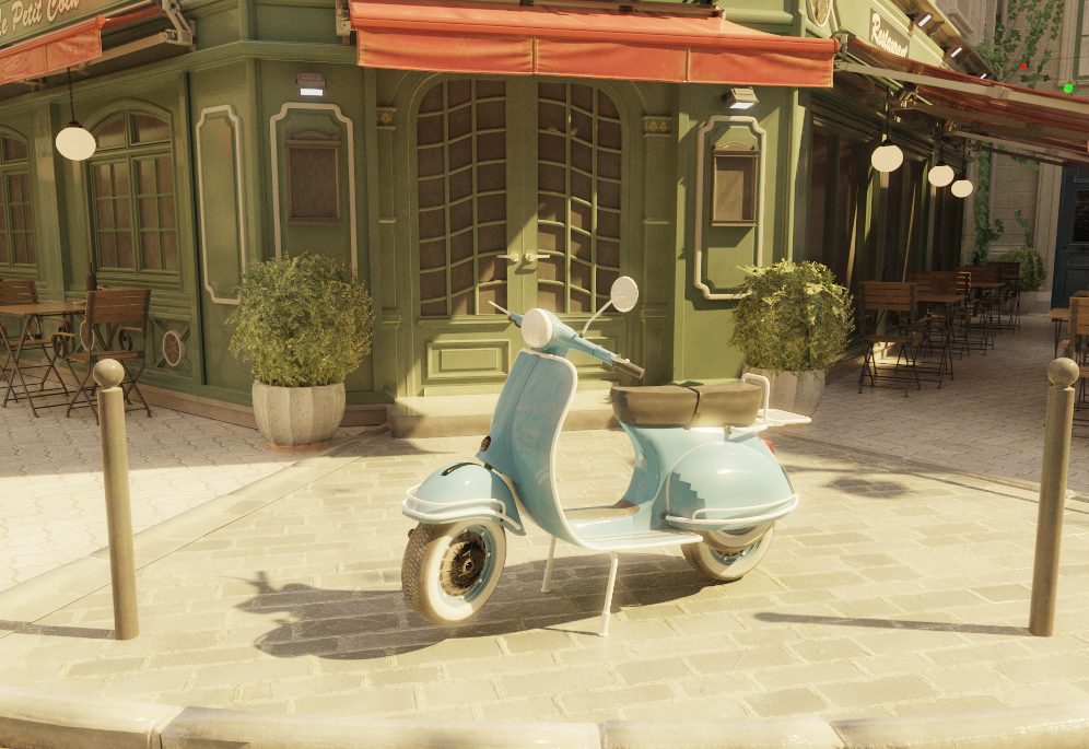
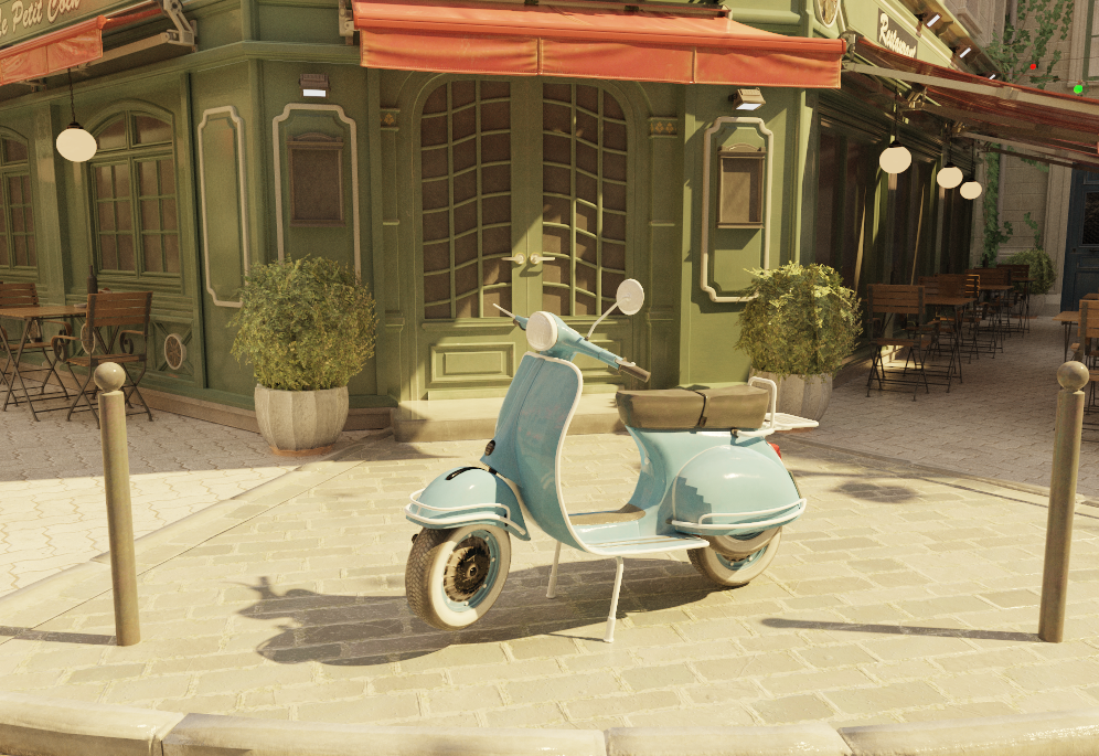 Bloom off
Bloom on
Bloom off
Bloom on
Scene: Nvidia Amazon Lumberyard Bistro (CC-BY 4.0)
Materials and Textures
The engine supports a full PBR material pipeline built on the Cook-Torrance microfacet model with a GGX normal distribution. Three material types are supported — Microfacet for the general case, Mirror for perfect specular surfaces, and Dielectric for glass and other transmissive materials. All are loaded automatically from OBJ/MTL files and can be overridden per-object in the Inspector.
Textures can drive any surface property spatially: base color, normal, emissive, roughness, metallic, and ambient occlusion maps are all supported. OBJ/MTL files use separate per-channel greyscale maps; glTF files typically pack roughness, metallic, and AO into a single ARM texture (R=AO, G=Roughness, B=Metallic). The engine handles both formats uniformly — ARM maps are deduped at the shared_ptr level so all three slots reference the same GPU texture object. When no texture is present, the scalar material value is used as fallback.
Every material property is live-editable in the Inspector without reloading the scene. A base color tint multiplies on top of the vertex or texture color — useful for quick color variations. An emissive strength multiplier scales the emissive contribution independently of the map, so you can dial a glowing surface from off to extremely bright at any time. Alpha clip can be toggled per-submesh. For Dielectric materials, an IOR preset popup offers one-click values for common materials (water, glass, crystal, diamond). Each texture slot shows a small inline thumbnail in the inspector, and hovering over one shows a proportionally-scaled preview — making it easy to verify which map is loaded without opening a file browser.
Material Types (from OBJ/MTL illum)
The engine maps OBJ/MTL fields to three internal material types. They can also be set manually in the Inspector.
| MTL condition | Type | materialType | BRDF |
|---|---|---|---|
| illum 0, 1, 2 (default) | Microfacet | 0 | Cook-Torrance GGX (diffuse + specular) |
| illum 3, 5 | Mirror | 1 | MirrorBSDF (delta, no NEE) |
| illum 4, 6, 7 | Dielectric | 2 | Fresnel reflect/refract (delta) |
d < 1 without alpha-clip texture |
Dielectric | 2 | Fresnel reflect/refract (delta) |
The dispatch also treats Microfacet materials with metallic > 0.99 and roughness < 0.01 as a perfect mirror shortcut via MirrorBSDF, avoiding numerical issues at near-zero GGX alpha.
PBR Parameter Mapping
| MTL property | PBR parameter | Notes |
|---|---|---|
| Pr | roughness | PBR scalar (0–1); used directly when present |
| Ns (shininess) | roughness | Fallback: clamp(1 - sqrt(max(Ns,0) / 1000), 0, 1) — inverts Blender's export formula Ns = (1−r)²×1000 |
| map_Pr | roughness texture | Preferred; expected in 0–1 PBR range |
| map_Ns | roughness texture | Fallback if map_Pr absent |
| Pm | metallic | PBR scalar (0–1); used directly when present |
| illum 3/5 | metallic | 1.0 (overrides Pm for mirror materials) |
| map_Pm | metallic texture | R channel sampled directly (0=dielectric, 1=metal) |
| Ni (IOR) | ior | Used directly for Dielectric (default 1.5) |
| Kd | baseColor | Vertex color (Ks for mirror; ignored for dielectrics — refraction is always clear) |
| d / Tr | materialType | d < 1 without alpha-clip texture → Dielectric (type 2) |
Roughness Range Examples
| Ns | Roughness | Appearance |
|---|---|---|
| 0 | 1.00 | Fully rough |
| 10 | 0.90 | Very rough |
| 100 | 0.68 | Moderately rough |
| 200 | 0.55 | Semi-rough (typical Blender interior material) |
| 500 | 0.29 | Fairly glossy |
| 1000 | 0.00 | Mirror-smooth |
Where Cook-Torrance is NOT Used
- Mirror (type 1) — Always dispatches to the delta MirrorBSDF (set by illum 3/5 in MTL or manually in the Inspector). Roughness and metallic are ignored. The surface albedo tints the reflection.
- Perfect mirror shortcut — Microfacet materials with
metallic > 0.99androughness < 0.01also dispatch to MirrorBSDF to avoid numerical issues at near-zero GGX alpha. - Dielectric (type 2) — Uses delta Fresnel reflect/refract (Snell's law). Refraction transmits with full throughput — the surface has no absorption, giving perfectly clear glass. Tinted glass would require Beer-Lambert attenuation over distance, which is left to the volumetric system. Rough dielectrics would need microfacet transmission — a separate feature.
Scene: Nvidia Amazon Lumberyard Bistro (CC-BY 4.0)
Resources
Some of the resources that influenced this project the most:
Foundations
- PBRT — The reference book on physically based rendering; covers BVH, microfacet theory, MIS, participating media, and more in full mathematical depth
- Ray Tracing in One Weekend — The classic starting point for writing a path tracer
- Scratchapixel — From-scratch derivations of ray tracing, Monte Carlo integration, and volume rendering math
BVH & Acceleration
- How to Build a BVH — Jacco Bikker — Hands-on multi-part series covering binned SAH construction and ordered traversal
Microfacet Theory & Sampling
- Understanding the Masking-Shadowing Function in Microfacet-Based BRDFs — Heitz 2014 — The mathematical foundation behind the GGX distribution and Cook-Torrance BSDF
- Sampling the GGX Distribution of Visible Normals — Heitz 2018 — The VNDF sampling paper used for the specular lobe
Vulkan & Hardware Ray Tracing
- vkguide.dev — Practical, modern Vulkan tutorial
- Nvidia Vulkan Ray Tracing Tutorial — Step-by-step guide to
VK_KHR_ray_tracing_pipeline, rgen/rmiss/rchit shaders, and TLAS/BLAS setup - LearnOpenGL — Comprehensive OpenGL tutorials
Advanced Ray Tracing
- Ray Tracing Gems I & II — Free books with in-depth chapters on sampling, denoising, participating media, and hardware ray tracing
This engine is an ongoing project — the roadmap above shows where it is headed. It covers the full stack from low-level GPU API work and acceleration structures to physically based shading and editor tooling, with every component built and understood by me.